What Is a One Phase Transformer and How Does It Work?
A One Phase Transformer is a compact device that changes alternating-current voltage through electromagnetic induction. Its primary winding receives electricity, while its secondary winding delivers a different voltage. The two windings share a magnetic core, but they usually remain electrically separated. That separation can improve safety and reduce unwanted disturbances.
John J. Winders Jr., author of Power Transformers: Principles and Applications, describes the core principle clearly: “A transformer transfers electrical energy from one circuit to another through electromagnetic induction.” The turns ratio controls the result. More secondary turns usually create higher voltage, while fewer turns reduce it. In a workshop, this may appear as a small metal enclosure, copper windings, gentle vibration, and a low hum under load. The device looks simple. It is not.
The International Energy Agency’s Electricity 2024 report expects global electricity demand to grow by about 3.4% annually through 2026. That growth increases pressure on reliable distribution equipment. The U.S. Department of Energy also estimates its 2024 distribution-transformer efficiency rule could save 3.6 quadrillion British thermal units over thirty years. Those figures show why transformer efficiency matters beyond a single building. Still, this introduction should not oversimplify the design. A One Phase Transformer loses energy through winding resistance, core losses, leakage reactance, and heat. Real performance depends on load, frequency, insulation, cooling, and installation quality. The ideal turns-ratio equation is useful. It is not the whole story.
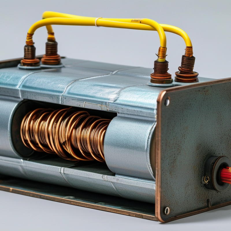
Definition and Core Parts: 120/240 V, 50/60 Hz Single-Phase Units
A one-phase transformer transfers electrical energy between circuits through electromagnetic induction. It changes voltage, but it does not change the supply frequency. In many residential and light-commercial systems, a single-phase unit delivers 120/240 V at either 50 or 60 Hz. The 240 V load connects across both outer terminals, while a 120 V load connects between one outer terminal and the center-tapped neutral.
The core is usually built from thin laminated steel sheets. These laminations reduce unwanted circulating currents and limit heat. Around the core sit two insulated windings: the primary receives incoming power, and the secondary supplies the adjusted voltage. Their turns ratio controls the voltage relationship. More secondary turns raise voltage; fewer turns lower it. Insulation, bushings, terminals, and a protective enclosure support safe operation. Small details matter.
During service checks, technicians look for loose terminals, unusual humming, cracked insulation, and excessive temperature. A slight hum can be normal. A sharp buzz deserves attention. The 50/60 Hz rating must match the intended system, especially when equipment moves between regions. The 120/240 V label also needs careful reading, because some units provide a center-tapped split-phase output while others use a different connection arrangement. The simple explanation works, but it is not complete. Actual performance also depends on load balance, connection method, ambient heat, and voltage drop. Misreading one terminal can create an expensive mistake.
| Data Dimension | Typical Specification or Value | Explanation |
|---|---|---|
| Basic Definition and Electrical Function | ||
| Transformer type | Single-phase transformer | A static electrical device that transfers alternating-current energy between circuits through electromagnetic induction. |
| Primary supply | 120 V or 240 V AC | The primary winding receives the input voltage. The exact voltage depends on the connection and the transformer design. |
| Secondary output | 120 V, 240 V, or 120/240 V AC | A center-tapped 120/240 V secondary can provide 120 V from either line to neutral and 240 V between the two line terminals. |
| Operating frequency | 50 or 60 Hz | The rated frequency must match the intended power system because frequency affects core flux, heating, and magnetizing current. |
| Energy transfer method | Mutual electromagnetic induction | An alternating current in the primary creates changing magnetic flux in the core, inducing voltage in the secondary winding. |
| Electrical isolation | Usually provided | In an isolated transformer, the primary and secondary windings are electrically separate while still coupled magnetically. |
| Voltage, Turns, and Current Relationships | ||
| Ideal voltage ratio | Vp/Vs = Np/Ns | The primary-to-secondary voltage ratio is approximately equal to the primary-to-secondary turns ratio. |
| Example turns ratio | 2:1 for 240 V to 120 V | A winding arrangement with approximately twice as many primary turns as secondary turns can reduce 240 V to about 120 V, subject to losses and regulation. |
| Ideal current relationship | Ip/Is = Ns/Np | For an ideal transformer, the lower-voltage winding carries higher current for the same apparent power. |
| Apparent power rating | VA or kVA | Transformer capacity is normally stated in volt-amperes because both voltage and current determine winding and core loading. |
| Typical small-unit ratings | 50 VA to 5 kVA | Small single-phase units commonly serve control circuits, lighting, appliances, instrumentation, and low-power distribution applications. |
| Voltage regulation | Load-dependent voltage change | The secondary voltage generally falls as load current increases because of winding resistance and leakage reactance. |
| Core Parts and Their Functions | ||
| Magnetic core | Laminated electrical steel | Provides a low-reluctance path for alternating magnetic flux. Laminations reduce eddy-current losses. |
| Primary winding | Insulated copper or aluminum conductor | Connects to the input supply and establishes the alternating magnetic flux in the core. |
| Secondary winding | Insulated copper or aluminum conductor | Receives induced voltage from the magnetic field and supplies power to the connected load. |
| Center tap | Optional neutral connection | A center-tapped secondary divides a 240 V winding into two approximately equal 120 V sections. |
| Winding insulation | Electrical insulation system | Separates turns, layers, and windings to prevent short circuits and withstand the specified voltage stress. |
| Bobbin or winding former | Insulating support structure | Supports and positions the windings while maintaining required clearances and insulation distances. |
| Terminals and leads | Input, output, and optional tap connections | Provide external electrical connections and identify the correct polarity, voltage, and grounding arrangement. |
| Enclosure | Open-frame or enclosed housing | Protects energized parts and may assist with cooling. The enclosure type must suit the installation environment. |
| Operating Characteristics and Safety | ||
| No-load secondary voltage | May exceed the nameplate voltage | Manufacturers may design for voltage drop under load, so the measured no-load voltage can be higher than the rated loaded value. |
| Efficiency | Typically high, load-dependent | Efficiency is reduced by copper losses in the windings, core losses, leakage flux, and auxiliary losses. |
| Main losses | Copper loss and core loss | Copper loss increases with load current, while hysteresis and eddy-current losses occur in the magnetic core during AC operation. |
| Grounding | System-dependent | Grounding and bonding must follow the applicable electrical code and the transformer’s wiring diagram; a neutral is not automatically the same as equipment ground. |
| Overcurrent protection | Required according to installation rules | Fuses or circuit breakers protect the transformer and conductors from excessive current and fault conditions. |
| Common applications | Lighting, control power, isolation, and small distribution | Single-phase transformers are used where the source and load are single-phase and where voltage conversion or isolation is needed. |
| Nameplate information to verify | Primary voltage, secondary voltage, frequency, VA/kVA, temperature class, and wiring diagram | These ratings determine whether the transformer is suitable for the intended supply, load, environment, and installation method. |